COLOR-CODE STANDARDS
Again, please bear with me... Let's start with simple pin-out diagrams of the two types of UTP Ethernet cables and watch how committees can make a can of worms out of them. Here are the diagrams:

Note that the TX (transmitter) pins are connected to corresponding RX (receiver) pins, plus to plus and minus to minus. And that you must use a crossover cable to connect units with identical interfaces. If you use a straight-through cable, one of the two units must, in effect, perform the cross-over function.
Two wire color-code standards apply: EIA/TIA 568A and EIA/TIA 568B. The codes are commonly depicted with RJ-45 jacks as follows (the view is from the front of the jacks):
 |  |
If we apply the 568A color code and show all eight wires, our pin-out looks like this:

Note that pins 4, 5, 7, and 8 and the blue and brown pairs are not used in either standard. Quite contrary to what you may read elsewhere, these pins and wires are not used or required to implement 100BASE-TX duplexing--they are just plain wasted.
However, the actual cables are not physically that simple. In the diagrams, the orange pair of wires are not adjacent. The blue pair is upside-down. The right ends match RJ-45 jacks and the left ends do not. If, for example, we invert the left side of the 568A "straight"-thru cable to match a 568A jack--put one 180° twist in the entire cable from end-to-end--and twist together and rearrange the appropriate pairs, we get the following can-of-worms:
This further emphasizes, I hope, the importance of the word "twist" in making network cables which will work. You cannot use an flat-untwisted telephone cable for a network cable. Furthermore, you must use a pair of twisted wires to connect a set of transmitter pins to their corresponding receiver pins. You cannot use a wire from one pair and another wire from a different pair.
Keeping the above principles in mind, we can simplify the diagram for a 568A straight-thru cable by untwisting the wires, except the 180° twist in the entire cable, and bending the ends upward. Likewise, if we exchange the green and orange pairs in the 568A diagram we will get a simplified diagram for a 568B straight-thru cable. If we cross the green and orange pairs in the 568A diagram we will arrive at a simplified diagram for a crossover cable. All three are shown below.
TUTORIAL: How to Make a Crossover Cable
This tutorial will show you how to properly conduct a Crossover network cable. This cable can be used to directly connect two computers to each other without the use of a hub or switch. The ends on a crossover cable are different from each other, whereas a normal 'straight through' cable has identical ends. Their uses are shown in the following diagrams.
WHAT YOU NEED
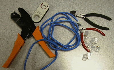
Cable- Be sure the cable(s) you are using is properly rated for CAT 5. It should state clearly on the jacket of the cable, what it is rated at. One option that you have when selecting your cable is to use a pre-made normal 'straight through' cable, and simply whack off one of the ends, and replace with a new "Crossed Over" end. For the purpose of this article, though, we aren't going to go that route. We are going to make the whole thing from scratch - using bulk CAT 5 cable.
Connectors - Crossover cables are terminated with CAT 5 RJ-45 (RJ stands for "Registered Jack") modular plugs. RJ-45 plugs are similar to those you'll see on the end of your telephone cable except they have eight versus four contacts on the end of the plug. Also, make sure the ends you select are rated for CAT 5 wiring. There are also different types of jacks which are used for different types of cabling (such as Solid Core wire). Make sure you buy the correct jacks for your cabling.
Crimper - You will need a modular crimping tool. My advice on what brand to get? Well, I really don't have a preference at this point, but make sure you buy a good one. If you spend about 40 to 50 bucks, you should have one that will last ya a lifetime. Spend 10 to 20 bucks, and you might be able to make a few cables with it if you're lucky. You definitely get what you pay for when it comes to crimpers!
Stripper - There are several specialized tools, which can be used to strip the jackets off of cabling. If you do not have access to one of these tools, cautious use of a razor blade or knife should work just fine - but keep in mind if you go the razor blade / knife route, extra special care must be used as to not damage the wires inside the jacket.
Cutters - You need a pair of cutters that will allow you to cut a group of cables in a straight line. It is very important that all the wires are the same lengths, and without proper cutters, this can be a difficult task.
---------------------------------------------------------------------
MAKING THE CABLE
1) - Start by stripping off about 2 inches of the plastic jacket off the end of the cable. Be very careful at this point, as to not nick or cut into the wires, which are inside. Doing so could alter the characteristics of your cable, or even worse render is useless. Check the wires, one more time for nicks or cuts. If there are any, just whack the whole end off, and start over.
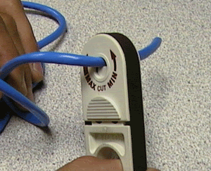
2) - Spread the wires apart, but be sure to hold onto the base of the jacket with your other hand. You do not want the wires to become untwisted down inside the jacket. Category 5 cable must only have 1/2 of an inch of 'untwisted' wire at the end; otherwise it will be 'out of spec'. At this point, you obviously have ALOT more than 1/2 of an inch of un-twisted wire, but don't worry - well take care of that soon enough.

3) - Up to this point, things have been pretty easy. Things will get a little bit tricky here, but don't worry, we'll get through this together. We are at a point in this article where a decision needs to be made. You need to decide which end of the cable you are making at this point in time. If you are making your cable from scratch like I am doing while writing this article, you have 2 end jacks, which must be installed on your cable. If you are using a pre-made cable, with one of the ends whacked off, you only have one end to install - the crossed over end. Below are two diagrams, which show how you need to arrange the cables for each type of cable end. Decide at this point which end you are making and examine the associated picture below.


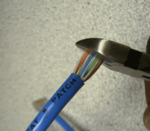
Begin to untwist the twisted exposed wires on your cable. Use caution so that you do not untwist them down inside the jacket. Once you have all the wires untwisted begin to arrange them in the proper order based on the pictures above. This stage can be a pain in the ass, especially some of the middle wires. Once you get all the wired arranged in the proper order, make sure your wire cutters are within reach then grasp them right at the point where they enter the jacket. Make sure you keep them in the proper order! Grab your cutters now. Line them up along your prepared wires about 1/2 inch above the jacket. Be sure at this point that you are both 1/2 inch above the jacket, and that your cutters are aligned straight across the wires. You want to make a clean cut here - also make sure you don't let go of that jacket / wires!
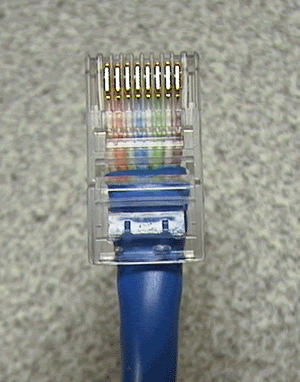
4) - Don't worry. From this point forward things get a lot easier. Grab your jack, and begin to slide the wires into the jack. Once you get to the point where the jacket begins to enter the jack things might get a little tough, but just have some patience and hold onto those wires. It will fit in there just fine. Once it is in as far as it will go the wires should extend almost to the front of the jack, and about 3/8 of an inch of the jacket will be inside the jack. Like the pictures below.
5) - Grab those crimpers - because not all crimpers are exactly the same your pictures may not match exactly what you see below. Be sure to keep a good grip on that jack and the cable. Insert the jack into the crimper. It should only go in one way, so you don't have a whole lot to worry about inserting it. Begin to compress those crimpers. You will more than likely hear a clicking sound. Keep squeezing. If you try to let go to early, nothing will happen. They will not release. Keep going until they stop clicking / stop moving all together. At this point, you should be able to let go of the jack, and the crimpers. The crimpers should release now leaving you with a crimped jack. If the crimpers do not release, you probably are a wimp and didn't press hard enough. Go ask your mom to help you at this point. She can probably finish what you started.
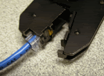

6) - It's time to examine what we have done. If you look at the end of the jack (distal), you should see that the copper connectors should not be pressed down into the wires. Toward the back of the jack (where the jacket meets the jack) it should be crimped securely holding the jacket / cable in the jack. If something has gone wrong, don't worry, its not the end of the world. Grab those cutters, and just whack the whole jack off and start back at step 1 (a pain in the ass I know, but its better to have a cable that works, than to spend hours trouble shooting your PC trying to figure out why you can't see the other machine). If everything is cool, all you have to do now is make the other end of the cable (unless you are using a pre-fab cable and have whacked one of the ends off), so go back to step one, and make the other end now.

---------------------------------------------------------------------
KEEP THIS IN MIND:
- Maximum Cable length for including connectors is 100 meters (or about 328 feet)
- Do not allow the cable to be sharply bent, or kinked, at any time. This can cause permanent damage to the cables' interior
- Do not overtighten cable ties
- Do not use excessive force when pulling cable through floors, walls or ceilings
- Do not use staples to secure category-5 cable, use the proper hangers, which can be found at most hardware stores
WHAT YOU NEED

Cable- Be sure the cable(s) you are using is properly rated for CAT 5. It should state clearly on the jacket of the cable, what it is rated at. One option that you have when selecting your cable is to use a pre-made normal 'straight through' cable, and simply whack off one of the ends, and replace with a new "Crossed Over" end. For the purpose of this article, though, we aren't going to go that route. We are going to make the whole thing from scratch - using bulk CAT 5 cable.
Connectors - Crossover cables are terminated with CAT 5 RJ-45 (RJ stands for "Registered Jack") modular plugs. RJ-45 plugs are similar to those you'll see on the end of your telephone cable except they have eight versus four contacts on the end of the plug. Also, make sure the ends you select are rated for CAT 5 wiring. There are also different types of jacks which are used for different types of cabling (such as Solid Core wire). Make sure you buy the correct jacks for your cabling.
Crimper - You will need a modular crimping tool. My advice on what brand to get? Well, I really don't have a preference at this point, but make sure you buy a good one. If you spend about 40 to 50 bucks, you should have one that will last ya a lifetime. Spend 10 to 20 bucks, and you might be able to make a few cables with it if you're lucky. You definitely get what you pay for when it comes to crimpers!
Stripper - There are several specialized tools, which can be used to strip the jackets off of cabling. If you do not have access to one of these tools, cautious use of a razor blade or knife should work just fine - but keep in mind if you go the razor blade / knife route, extra special care must be used as to not damage the wires inside the jacket.
Cutters - You need a pair of cutters that will allow you to cut a group of cables in a straight line. It is very important that all the wires are the same lengths, and without proper cutters, this can be a difficult task.
---------------------------------------------------------------------
MAKING THE CABLE
1) - Start by stripping off about 2 inches of the plastic jacket off the end of the cable. Be very careful at this point, as to not nick or cut into the wires, which are inside. Doing so could alter the characteristics of your cable, or even worse render is useless. Check the wires, one more time for nicks or cuts. If there are any, just whack the whole end off, and start over.

2) - Spread the wires apart, but be sure to hold onto the base of the jacket with your other hand. You do not want the wires to become untwisted down inside the jacket. Category 5 cable must only have 1/2 of an inch of 'untwisted' wire at the end; otherwise it will be 'out of spec'. At this point, you obviously have ALOT more than 1/2 of an inch of un-twisted wire, but don't worry - well take care of that soon enough.

3) - Up to this point, things have been pretty easy. Things will get a little bit tricky here, but don't worry, we'll get through this together. We are at a point in this article where a decision needs to be made. You need to decide which end of the cable you are making at this point in time. If you are making your cable from scratch like I am doing while writing this article, you have 2 end jacks, which must be installed on your cable. If you are using a pre-made cable, with one of the ends whacked off, you only have one end to install - the crossed over end. Below are two diagrams, which show how you need to arrange the cables for each type of cable end. Decide at this point which end you are making and examine the associated picture below.


Begin to untwist the twisted exposed wires on your cable. Use caution so that you do not untwist them down inside the jacket. Once you have all the wires untwisted begin to arrange them in the proper order based on the pictures above. This stage can be a pain in the ass, especially some of the middle wires. Once you get all the wired arranged in the proper order, make sure your wire cutters are within reach then grasp them right at the point where they enter the jacket. Make sure you keep them in the proper order! Grab your cutters now. Line them up along your prepared wires about 1/2 inch above the jacket. Be sure at this point that you are both 1/2 inch above the jacket, and that your cutters are aligned straight across the wires. You want to make a clean cut here - also make sure you don't let go of that jacket / wires!

4) - Don't worry. From this point forward things get a lot easier. Grab your jack, and begin to slide the wires into the jack. Once you get to the point where the jacket begins to enter the jack things might get a little tough, but just have some patience and hold onto those wires. It will fit in there just fine. Once it is in as far as it will go the wires should extend almost to the front of the jack, and about 3/8 of an inch of the jacket will be inside the jack. Like the pictures below.

5) - Grab those crimpers - because not all crimpers are exactly the same your pictures may not match exactly what you see below. Be sure to keep a good grip on that jack and the cable. Insert the jack into the crimper. It should only go in one way, so you don't have a whole lot to worry about inserting it. Begin to compress those crimpers. You will more than likely hear a clicking sound. Keep squeezing. If you try to let go to early, nothing will happen. They will not release. Keep going until they stop clicking / stop moving all together. At this point, you should be able to let go of the jack, and the crimpers. The crimpers should release now leaving you with a crimped jack. If the crimpers do not release, you probably are a wimp and didn't press hard enough. Go ask your mom to help you at this point. She can probably finish what you started.


6) - It's time to examine what we have done. If you look at the end of the jack (distal), you should see that the copper connectors should not be pressed down into the wires. Toward the back of the jack (where the jacket meets the jack) it should be crimped securely holding the jacket / cable in the jack. If something has gone wrong, don't worry, its not the end of the world. Grab those cutters, and just whack the whole jack off and start back at step 1 (a pain in the ass I know, but its better to have a cable that works, than to spend hours trouble shooting your PC trying to figure out why you can't see the other machine). If everything is cool, all you have to do now is make the other end of the cable (unless you are using a pre-fab cable and have whacked one of the ends off), so go back to step one, and make the other end now.

---------------------------------------------------------------------
KEEP THIS IN MIND:
- Maximum Cable length for including connectors is 100 meters (or about 328 feet)
- Do not allow the cable to be sharply bent, or kinked, at any time. This can cause permanent damage to the cables' interior
- Do not overtighten cable ties
- Do not use excessive force when pulling cable through floors, walls or ceilings
- Do not use staples to secure category-5 cable, use the proper hangers, which can be found at most hardware stores


No comments:
Post a Comment