 LANshack.com was the very first ecommerce website to offer free online tutorials for cable connections. To say that our articles have been popular over the span of many years would be an understatement. But time marches on and we now have three major updates. For one, we have updated this very popular tutorial, and two, we now have a video tutorial to go with it. But most importantly, we have now developed a totally new system for termination cables called the QuickTreX™ PRO System™.
 Wow! After over 10 Years of working with cables, tools and connectors, and after keeping on top of our tool, cable, and connector suppliers, we have put it all together to formulate this system for the present a future of cabling components. What does all this mean to the consumer?Compatibility, Reliability, Dependability, ease of use and virtually fool-proof and repeatable results.
Due to an overwhelming response to our category 5 & 6 tutorial, and many requests for information and wiring diagrams of "straight through" and "crossover" (cross-pinned) patch cords, I have made this informational page and technical video. On this page, we will cover making patch cords, and other technical and non-technical issues relating to category 5 and 6 patching and connectivity from device to device. Below, you will find the diagrams for 568A, 568B, and crossover patch cables. I suggest that you read on, past the diagrams for some very useful and important information.
As always, there continues to be Controversies over standards and practices regarding the use and making of patch cords, and UTP cable in general. Please see our section below titled: "Controversies and Caveats : Category 5, 5E, and Cat 6 Patch Cables". I hope that you will find it interesting and informative.
--Tony Casazza, RCDD
 | 568-B Wiring
|  | 568-A Wiring
| ||||||||||||||||||||||||||||||||||||||||||||||||||||
Notes For Wiring Diagrams Above:
2. There is no difference in connectivity between 568B and 568A cables. Either wiring should work fine on any system*. (*see notes below)
3. For a straight through cable, wire both ends identical.
4. For a crossover cable, wire one end 568A and the other end 568B.
5. Do not confuse pair numbers with pin numbers. A pair number is used for reference only (eg: 10BaseT Ethernet uses pairs 2 & 3). The pin numbers indicate actual physical locations on the plug and jack.
Patch Cable Assembly Instruction.
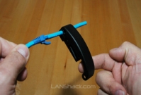
 1. Cut the cable to the length that you will need.
If you are planning to use boots, this would be a good time to slip them on.
Place each boot facing out on the cable.
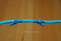
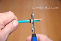
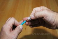
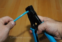
 2. Skin the cable about 1.5down.
For fast and dependable skinning we recommend our QuickTreX™ EZ Cable stripper.
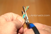
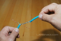 3. Remove all of the twists in the cables pairs.
TEC-TIP: Use a piece of the removed insulation to make it easy to remove the twists from each pair.
Un-twist each pair, and straighten each wire between the fingers.
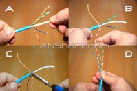 4. Cat 6 cable has a center spine that needs to be removed.
Pull on the spine and fold the pairs back.
Then cut the spine as close to the cables end as possible.
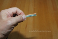
 5. Place the wires in the order of one of the two diagrams shown above (568B or 568A).
Here we have chosen the 568B diagram which is by far the most popular.
If you are unsure, go with the 568B wiring.
 6.Bring all of the wires together, until they touch.
Hold the grouped (and sorted) wires together tightly, between the thumb, and the forefinger.
At this point, recheck the wiring sequence with the diagram.
 7.TEC-TIP: Cut the wires on a very sharp angle to make it easier to install the load-bar(in the next step).
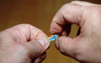 8.Insert the loadbar on the wires one wire at a time.
This is why we recommended cutting the wires on an angle.
We recommend our QuickTreX™ connectors with load bar for the best results..
 9.Check the wiring sequence one more time.
Than slide the load bar down all the way and make a straight cut about 0.25 past the loadbar.
A perfectly straight cut is essential here.
That is why we strongly recommend our new QuickTreX™ Wire Surgeon Electricians Scissors.
 10.Insert the connector onto the load bar assembly.
Hold the plug with the copper connectors up and the locking clip facing down.
In this configuration, the Brown Pair of wires should be to the right side
(see diagram on the right)
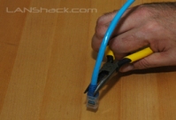
 11.For Crimping we recommend our QuickTreX™ Ratchet Crimper for RJ-45 and RJ-11/12..
Push the connector all of the way in and then squeeze down all the way on the crimper.
Remove the connector from the crimper body.
 12.Slide the boots (if used) all the way up to the connector.
If necessary, use a tapping motion as shown in the illustration.
13.Repeat the procedure on the other end of the cable using the same wiring diagram. NOTE: If you wish to make a crossover cable, than use the other diagram (in this case 568-A)
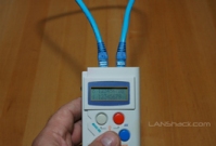 14.Test the cable using a high quality four pair tester.
For this we recommend our LANTEST-PRO Cable Tester.
Notes Regarding Making Category 5 Patch Cable
2)Ordinarily, it would be taboo to untwist the pairs of any category 5 or 6 cable. The one exception to this rule is when crimping on RJ-45 plugs. It would be impossible to insert the wires into the channels without first untwisting and straightening them. Be sure not to extend the un-twisting, past the skin point. If you do it properly, you will wind up with no more than 1/2" of untwisted conductors (up to 1/2" of untwist meets the cat 5 or 6 specification).
3)If the completed assembly does not pass continuity, you may have a problem in one, or both ends. First try giving each end another crimp. If that does not work, then carefully examine each end. Are the wires in the proper order? Do all of the wires fully extend to the end of the connector? Are all of the pins pushed down fully. Cut off the suspected bad connector, and re-terminate it. If you still have a problem, then repeat the process, this time giving more scrutiny to the end that was not replaced.
No comments:
Post a Comment